Static Margin Aircraft - An additional effect is that for a given attitude change, the change in rate of climb is proportional to the true airspeed. Thus, for an attitude change for 500 ft per minute (fpm) at 290 knots indicated air speed (kias) at sea level, the same change in attitude at 290 kias (490 knots true air speed) at 35,000 ft would be almost 900 fpm
. This characteristic is essentially true for small attitude changes, such as the kind used to hold altitude. It is also why smooth and small control inputs are required at high altitude, particularly when disconnecting the autopilot.
Static Margin Aircraft
![Propulsion Assembly For An Aircraft, Comprising A Load Support Auge; Philippe ; Et Al. [Airbus Operations Sas]](https://uspto.report/patent/app/20200189759/US20200189759A1-20200618-D00000.png)
Hi sorry, the formulation to find the "D" or therefore the NP seems wrong when compared to http://chrusion.com/BJ7/SuperCalc7.htmlThe formulation pushes the NP far too back and therefore causing massive tail heavy on its final CG setup, try it yourself.
CG is never given as a fixed location because it changes with loading of the aircraft and other parameters. The control free neutral point is the CG location at which the control free pitch stiffness vanishes.
That means that the control free point moves when the CG changes. The fixed static margin can be stick-free or stick-neutral and changes with CG, but also with elevator area. In aircraft design there are some critical measures that will determine if your plane will fly.
Those measures are the Static Margin (SM), Center of Gravity (CG), Horizontal Stabilizer Volume (VH), Vertical Stabilizer Volume (VV), and Cubic Wing Loading (CWL). When power is concerned, the additional measures of Power-to-Weight Ratio (P/W) and Thrust-to-Weight Ratio (T/W) are very important.
In order to find these key measures we must first find a few other measures before hand. These measures would be the dimensions and areas of the main wing, horizontal and vertical stabilizers, the aerodynamic centers (AC), Neutral Point (NP), and the distance between the two centers.
Don't worry about the AC and NP yet, I'll show you how to find them! When finding the area and dimensions, the critical ones are the labeled dimensions A (Root Chord), B (Semi-Span), & C (Tip Chord) in the picture below;
Reply 5 years ago For a given aircraft, the higher its aspect ratio for a given wing area, the shorter the chord will become. Hence the MAC will also be smaller. This will in turn reduce the absolute value of the allowable range for the static margin.

When airplanes are operated near the aft CG limit, download on the tail is minimized and angles of attack and drag are reduced. However, moving the CG aft reduces the longitudinal static stability of the airplane, something that all flight crews should be aware of (figure 1).
Hey Guys, My friends at Dual Design R/C and I wanted to give you all open-ended step-by-step instructions on how to design a basic airplane with a large degree of artistic freedom and easy mathematics! You will need to watch the units you use!
No crazy engineering needed here. I'll be using an example of a conventional airplane with the main wing in front of the stabilizers (Stab). I'll also be using simple tapered wings to keep complexity low. Instead of using an absolute value for the allowable range of the static margin, it is expressed as a percentage of the Mean Aerodynamic Chord (MAC) - for example between 5 and 30%.
Why is this so? Question 4 years ago on Step 1 Next Stop, Neutral Point! (NP) With the AC of all your wing panels found, we can find the NP of your airplane. The NP is like the AC of your entire airplane.
With your drawing ready, measure L (The distance between the AC of the Main Wing and Horizontal Stab.) and use that in addition to the areas of both to find the length D. The equation is listed in the middle of the three in the
picture below. We can now use D to find the location of NP by subtracting it from L. Since download on the tail is negative lift, effectively increasing the weight of the airplane, the location of the CG affects the cruise performance of any airplane.
Flying at an aft CG will reduce the download on the tail and improve cruise performance. Maneuvering stability, like static stability, is influenced by CG location. However, when the CG is aft and near the neutral point, then altitude also has a significant effect.
Since air density has a notable impact on the damping moment of the horizontal tail, higher pitch rates will result in the same elevator deflections as altitude increases. From the flight crew's perspective, as altitude increases, a pull force will result in a larger change in pitch angle, which translates into an increasing angle of attack and g. While a well-designed flight control system, either mechanical or electronic, will reduce

the variation of stick force with CG and altitude, it is very difficult to completely eliminate the variation due to design limitations. Normally, the tail lever arm is also chosen as a multiple of MAC. A higher wing chord means more tail force is needed in order to set the correct angle of attack.
If you compare different airplanes, you will notice that the relative size of the horizontal tail goes down with a higher wing aspect ratio. While GA airplanes have horizontal tails sized to between 20% and 25% of their wing surface, gliders have horizontal tails of around 10% to 15%.
It must be said, however, that gliders need less flexibility in their cg location, which is another reason for reducing horizontal tail size. Great! Now we can find the location of the Center of Gravity (CG).
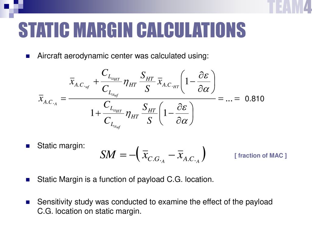
This is found by determining the Static Margin. The Static Margin is a measure of stability of your plane. Typically the SM is a distance based on the length of the GMC or MAC. Most planes have a SM of 5% to 15% of the MAC which means the CG is 5% MAC to 15% MAC in front of the NP.
A plane with a Static Margin of 5% is limited in stability and 15% is great stability. Never put the CG behind the NP!!!!! Just don't do it! You've been warned. Awesome! We have NP, ACs, and CG found.
What is next? the Tail Volumes! What are they? They are a measure of the effectiveness of the stabilizers. We'll start with the horizontal stabilizer. Using the Areas, Lengths, and MAC use the equation at the top of the first picture below to find the Horizontal Stabilizer Volume (VH).
Typical values for this are between .35 and .8. .35 is less effective and .8 is SUPER effective. "Everything that explains the world has in fact explained a world that does not exist, a world in which men are at the center of the human enterprise and women are at the margin "helping" them.
Such a world does not exist—never has.”—Gerda Lerner (b. 1920) The differences in the two fields arise largely from the use of cambered wings in aircraft. Missiles are symmetrical vehicles and if they have airfoils they too are symmetrical.

With cambered wings the location of the center of pressure on the wing is a strong function of the angle of attack - see movement of the center of pressure. With the introduction of computers into airplane flight control design, other aerodynamic improvements are possible.
However, because these improvements may affect airplane stability, flight crews should be aware of how CG and altitude affect the performance and handling characteristics of the airplanes they fly. This requires an understanding of the following key concepts:
For example, for the same control surface movement at constant airspeed, an airplane at 35,000 ft (10,670 m) experiences a higher pitch rate than an airplane at 5,000 ft (1,524 m) because there is less aerodynamic damping.
The pitch rate is higher, but the resulting change in flight path is not. Therefore, the change in angle of attack is greater, creating more lift and more g. If the control system is designed to provide a fixed ratio of control column force to elevator deflection, it will take less column force to generate the same g as altitude
increases. Are these guys still on? I can't understand about .02 or .05 is it 0.05 or 0.02? BTW I calculate with VV formula and it's ended up with 0.1 ... Am I doing something wrong?
The stick-fixed margin is much easier to calculate. If the aspect ratio is reasonably high, the surface-weighted mean of the quarter points of all horizontal surfaces will give a good approximation of the neutral point $x_N$, and the center of gravity depends on the loading of the aircraft.
Normally, you would calculate the margin for both the most forward and the most backward cg location $x_S$ for which the aircraft is certified. I hope you gain some great information from this article. It summarizes my understanding of aircraft design and hopefully helps others as well.
Now, the next step is for you to build your creation! I would suggest a boxy foam and tape method much like timcarlielle and tak145 did here in instructables. Feel free to comment, PM, or email me with further questions or requests.

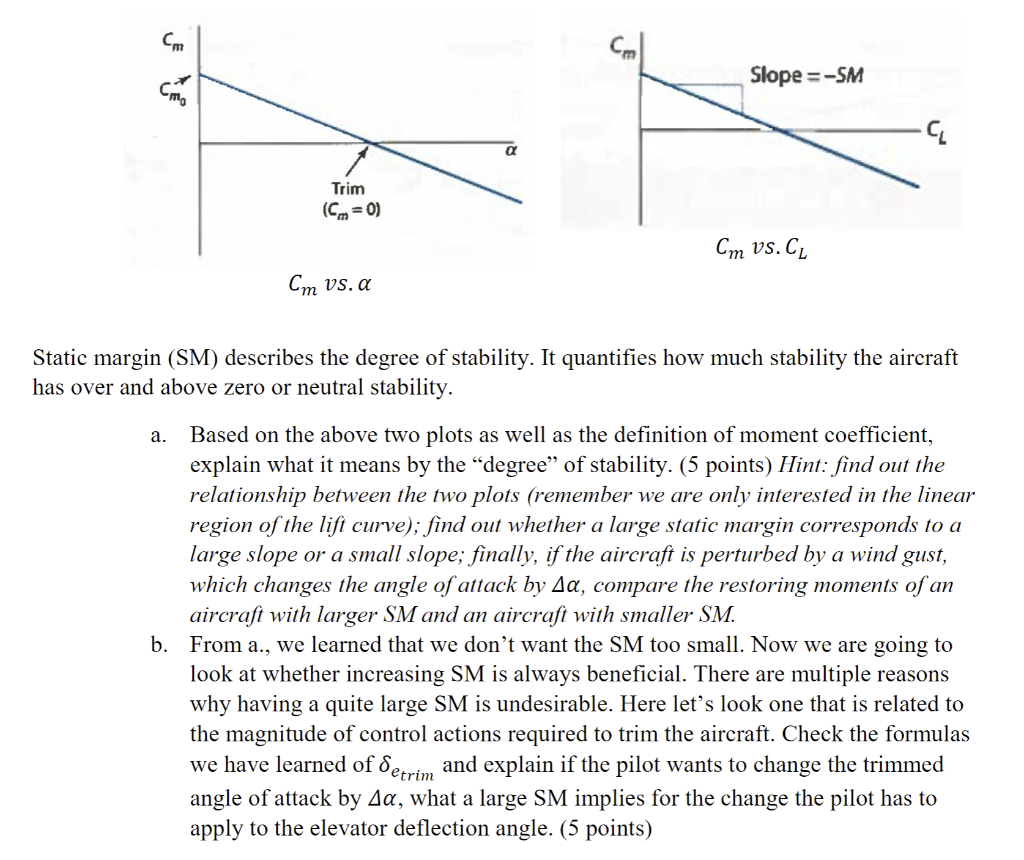
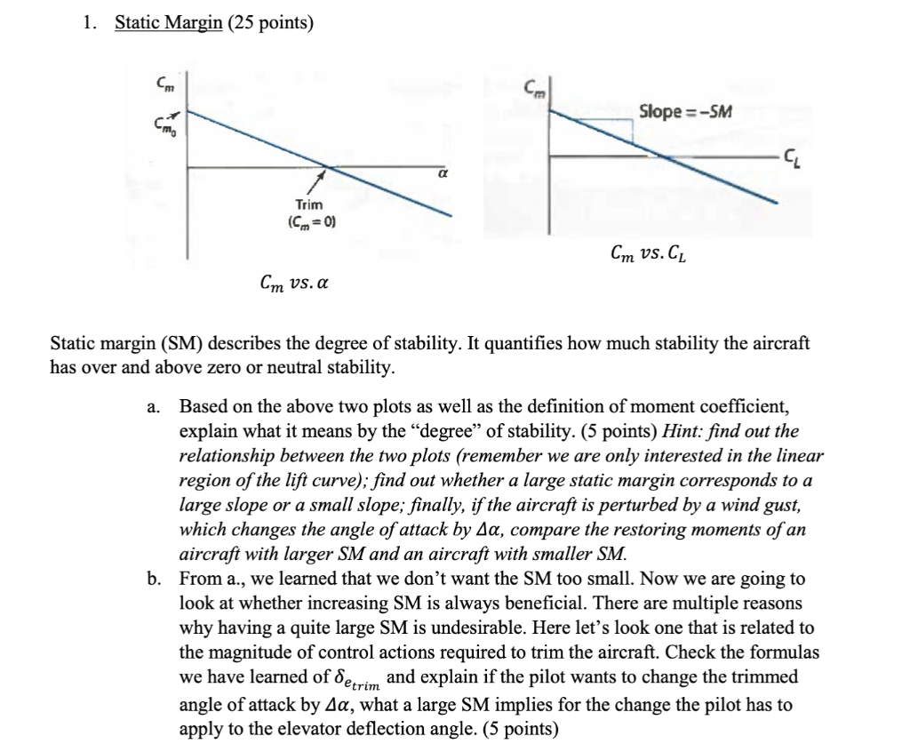
Also, thanks to my friends over at Dual Design R/C for confirming my thoughts and helping me in writing this article. FlyBoy38L If an aircraft in flight suffers a disturbance in pitch that causes an increase (or decrease) in angle of attack, it is desirable that the aerodynamic forces on the aircraft cause a decrease (or increase) in angle of attack so that the disturbance does not
cause a continuous increase (or decrease) in angle of attack. This is longitudinal static stability. The Boeing 777 uses redundant digital flight control computers to provide positive (static longitudinal) stability and enhances that stability with airspeed feedback.
The MD-11 uses computers to provide neutral speed stability. In other words, the CG of the MD-11 appears to be at the neutral point. The MD-11 uses elevator deflection to hold attitude at any speed within the normal flight envelope, then trims the stabilizer.
This is known as an "attitude hold" system. Augmented stability provides better cruise performance with no increase in workload and no adverse effects from flying at an aft CG. This technology also allows for a smaller tail size, which further reduces drag and weight.
However, FAR Part 25 requires that handling qualities remain adequate for continued safe flight and landing following an augmentation system failure. Therefore, a practical limit exists for how far aft the CG can go. The stick-free static margin depends a lot on the elevator hinge moment coefficients of the aircraft.
Depending on the sign of the hinge moment derivative with angle of attack ($c_{r_\alpha}$), the stick-free stability can be greater than the stick-fixed stability (greater for positive $c_{r_\alpha}$ because then the control surface will deflect into the changed airflow).
By how much depends also on the derivative over deflection angle $c_{r_\eta}$, but this one should definitely stay in the negative range, or the stick will be hard to center. The trend in the design of modern airplanes is to have less static longitudinal stability--frequently referred to as relaxed static stability (RSS)--to capture the benefit of improved fuel efficiency.
Simply stated, some airplanes are now designed to be aerodynamically efficient, and stability is augmented electronically so that stick force gradients will meet certification requirements. Many methods exist for increasing stability. For example, the Boeing 777 and MD-11 use flight control computers that adjust the elevator actuator positions to give the appearance of more longitudinal stability than the airplane actually has.

In other words, computers absorb the extra workload caused by flying with RSS. This principle is the essence of high-altitude handling characteristics for RSS airplanes. Unless an RSS airplane has an augmentation system to compensate for its maneuvering stability, lighter column forces are required for maneuvering at altitude.
Longitudinal maneuvering requires a pitch rate, and the atmosphere provides pitch rate damping. As air density decreases, the pitch rate damping decreases, resulting in decreased maneuvering stability (figure 2). Now we can move onto finding the Vertical Stabilizer Volume (VV).
Below is a photo of how to find VV. Using the areas and distances once again, use the equation listed above and find VV. Typical values for VV are between .02 and .05. Once again .02 is a less effective tail and .05 is a SUPER effective tail.
Answer 4 years ago In flight, the wings of a conventional airplane generate a nose down pitching moment. To balance this, a download is required on the tail. Airplanes loaded with an aft forward CG require less download on the tail.
With the center of gravity forward of the neutral point, an aircraft has positive longitudinal static stability. (For an aircraft this may be described as negative static margin.) With the center of gravity aft of the neutral point, an aircraft is statically unstable, and requires some form of augmentation to be flown with an acceptable workload.
(For an aircraft this may be described as positive static margin.) To start out analyzing your design you'll need a 3 view drawing of your plane on a piece of paper. I suggest a scale drawing on a piece of graph paper.
Keep it simple, and keep it boxy. Boxy is easier to build! Here is a great example below. For missiles, positive static margin implies that the complete vehicle makes a restoring moment for any angle of attack from the trim position.
If the center of pressure is behind the center of gravity, then the moment will be restored. For missiles with symmetric airfoils, the neutral point and the center of pressure are coincident and the term neutral point is not used.
static margin formula, negative static margin, neutral point of aircraft, calculate aircraft cg, how to calculate static margin, stability margin aircraft, aircraft static stability, rutan long ez for sale
0 Comments